Using a BellaTek Copy Milled Framework to solve a tricky case
Non-optimally positioned implants can significantly impede the ability of restorative dentists and their laboratory partners to deliver functional and esthetic restorations.
Non-optimally positioned implants can significantly impede the ability of restorative dentists and their laboratory partners to deliver functional and esthetic restorations.
However, advanced CAD/CAM technology is making it increasingly possible to effectively restore even significantly malpositioned implants.
The following case study illustrates how eight implants from three different manufacturers, which were placed at different times, were not well aligned. Nonetheless, the implants were able to be restored with a CAD/CAM framework (BellaTek® Copy Milled Framework, BIOMET 3i). Frameworks milled from solid titanium have been shown to fit more accurately than cast frameworks and are biocompatible.1, 2
The Case
01 A 55-year-old male patient presented with a removable overdenture supported by implants from three different manufacturers (two 6 mm BIOMET 3i Certain® Implants, five Zimmer 4.5 mm Screw-Vents, and one 4.0 mm Calcitek Spline) (Fig. 1). The implants had been placed at different times, by different dentists. The angulations of the implants were severely compromised, with implant thread exposure and soft-tissue recession on several implants (Fig. 2). The patient was known to have a severe gag reflex and was a bruxer with a low lip line. The treatment plan requested by the patient was for a fixed maxillary restoration.


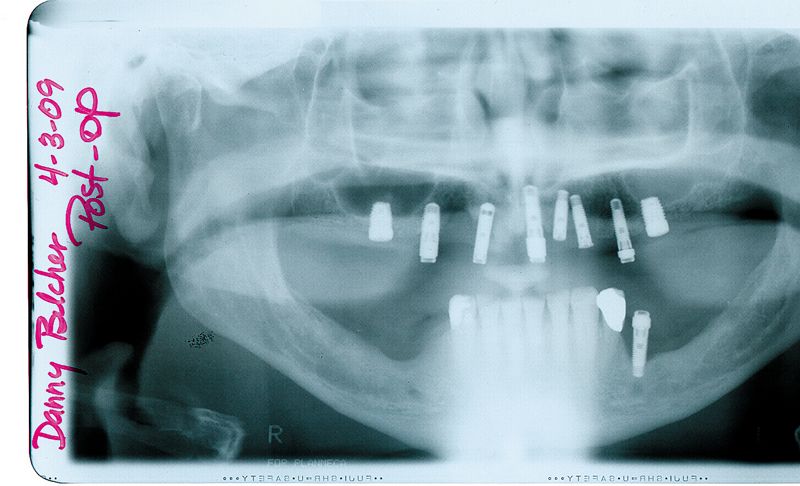


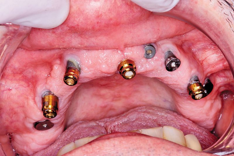


Fig. 2?Initial intraoral clinical view.
Fig. 3?The implant impression copings in place.
02 The restorative dentist removed the pre-existing restorative components and made a pick-up impression, using the appropriate non-engaging impression copings for each of the three implant systems (Fig. 3).
03 In the dental laboratory, implant-specific analogs were mated to their respective impression copings in the impression. A master cast was poured in die stone. For complex cases, it is well known that master casts should be verified. In this case, the non-engaging implant impression copings were placed onto their respective implant analogs in the master cast, and dental floss was intertwined around the impression coping bodies (Fig. 4).
04 To complete fabrication of the verification index, GC Pattern Resin (GC America) was applied to the floss/impression coping assemblies in small increments (Fig. 5). Once the resin set, all of the impression coping screws were removed, except for one. Complete metal-to-metal fit (impression coping/analog) was verified.
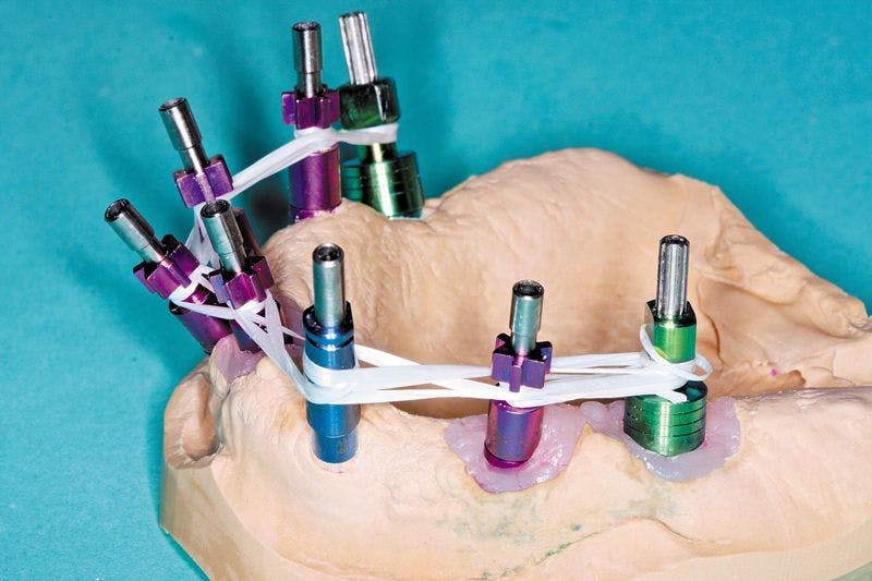

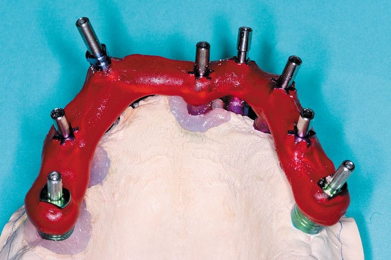

Fig. 4?Dental floss intertwined around the impression copings on the master cast.
Fig. 5?The completed verification index.
05 In the restorative office, the dentist tried the verification index onto the implants with the one-screw test. He noticed the fit was not accurate (complete metal-to-metal contact was not visible). He sectioned the verification index, noted that all of the copings fit the implants, and then reapplied GC Pattern Resin to connect all of the segments.
06 Another impression, including the verification index, was made and sent back to the lab. New implant analogs were mated to their respective impression copings, and another master cast was fabricated. The verification index was removed from the master cast, and the one-screw test was done again. This time the fit was accurate. A maxillary record base and occlusion rim was made on it and returned to the dentist for jaw-relation records. The record base was returned to the laboratory, and the casts were mounted (Fig. 6).

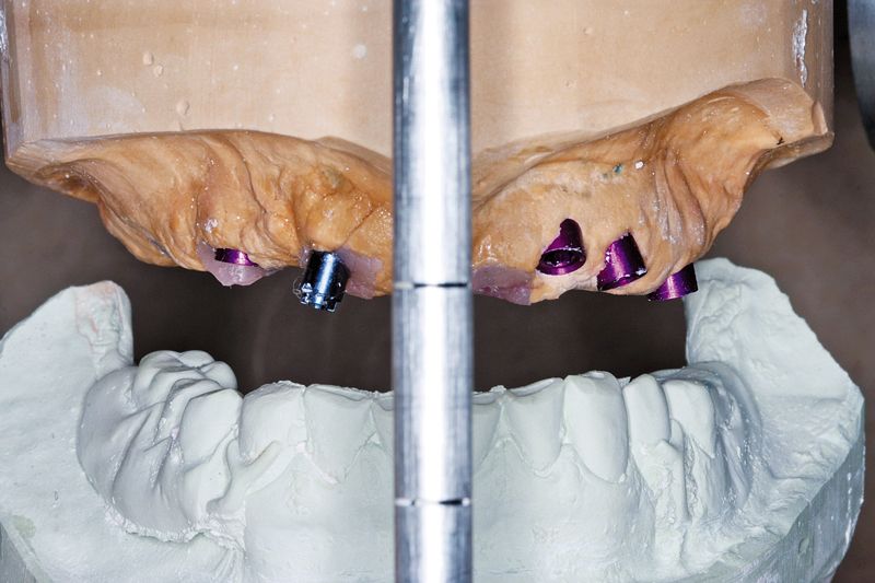

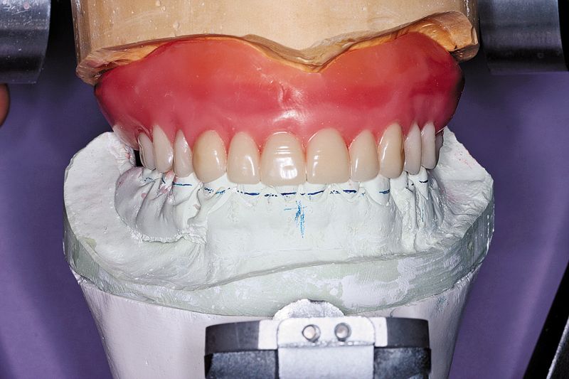

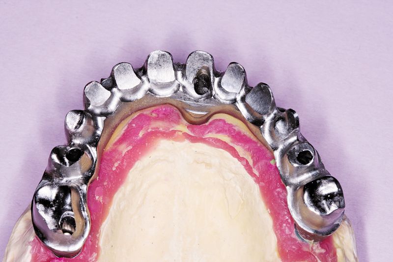
Fig. 6?The casts were mounted on an articulator.
Fig. 7?A wax denture was fabricated.
Fig. 8?The BellaTek Copy-Milled Framework mounted on the master cast with the soft-tissue replica in place.
07 Using conventional denture-fabrication principles, denture teeth were set (Fig. 7). The wax denture was tried in. The patient approved the esthetics, and the dentist confirmed the occlusal relationships. The wax denture was re-contoured for use as a screw-retained acrylic-resin hybrid framework (for copy-milling). The maxillary master cast, the verification index, the copy-mill wax pattern, and the signed work order were sent to the BellaTek Production Center at BIOMET 3i.
08 The wax pattern was scanned, and a BellaTek Framework was milled from a solid blank of titanium. The framework was returned to the laboratory where the framework was tried onto the master cast (Fig. 8).
Next page: Finalizing the case.
09 The patient had lost a significant amount of soft and hard tissue in the maxillary arch. To recreate the missing soft-tissue volume, the BellaTek Copy-Mill Framework was masked with an opaque, and zirconium silicate microceramic material (Ceramage, Shofu) was applied (Figs. 9 and 10). This material is available in an assortment of gingival colors that correspond to color variations in the natural dentition. The gingival mask was finished with standard abrasives such as stones and rubber wheels and polished.
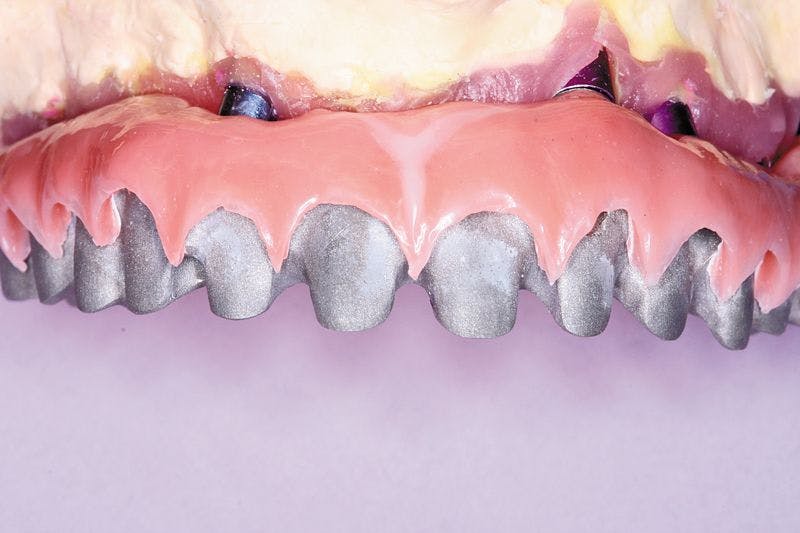

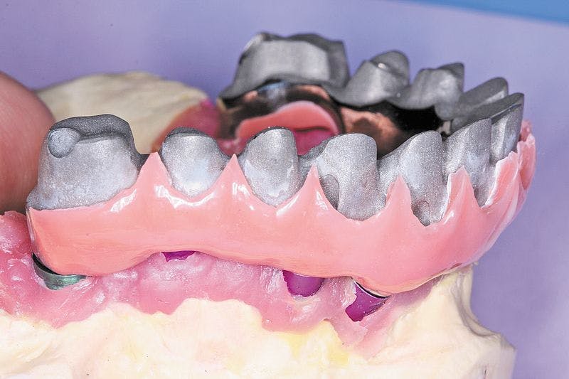

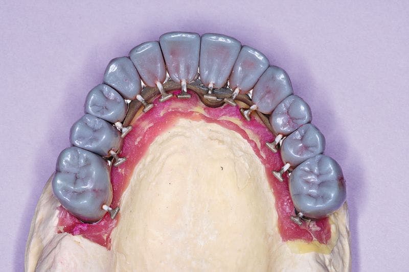

Fig. 9?Facial view of the gingival microceramic material on the framework.
Fig. 10?Lateral view of the gingival microceramic material on the framework.
Fig. 11?Full contour wax patterns seated on the BellaTek Framework.
10 The copy-milled framework was duplicated, using a silicone-duplicating material that was mixed, poured into a duplicating flask, and put under pressure at 4 bars for 40 minutes. The model was removed from the silicone, and a new master cast was fabricated in die stone. Individual full-contour wax patterns were cast in Galileo (Jensen) (Fig. 11). These were finished, put back on the individual dies (Fig. 12), and the full contours of the teeth were re-established in wax. This set of wax patterns was then invested, and a pressable ceramic porcelain system was used to fabricate the all-ceramic crowns (Authentic, Jensen).

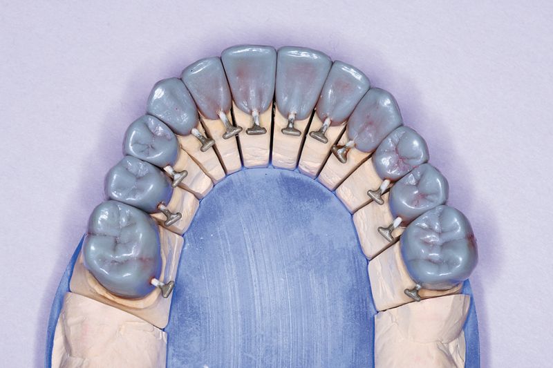
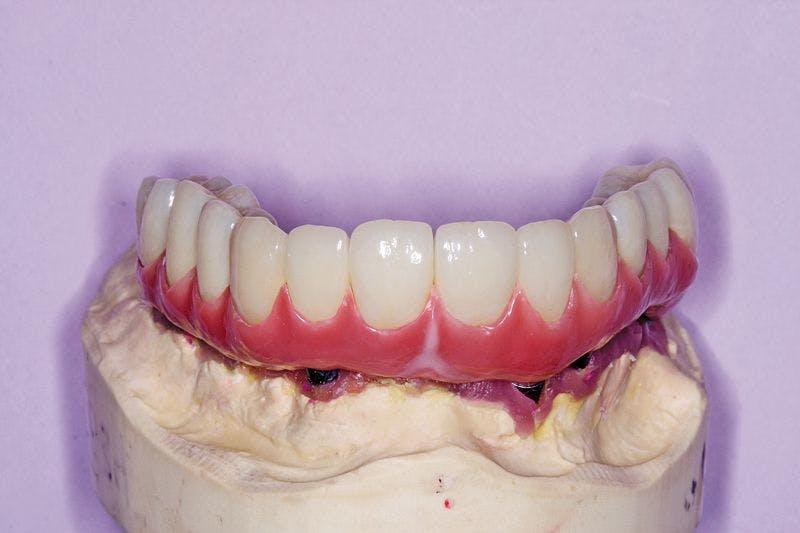

Fig. 12?Full contour was patterns on the individual dies.
Fig. 13?The crown restorations in place on the BellaTek® Copy-Milled Framework.
11 The restoration and remaining crowns were returned to the dentist (Fig. 13). The BellaTek Framework was seated intraorally and secured with manufacturer-specific abutment screws. These were tightened to the appropriate torque per each manufacturer’s instructions. The implant-supported crowns corresponding to tooth Nos. 5, 8, and 12 were cemented with NX3 Cement (Kerr) while tooth Nos. 3, 4, 6, 7, 9, 10, 11, 13 and 14 were cemented with temporary cement so the screws could be accessed for removal, if necessary (Fig. 14). A panoramic radiograph was taken (Fig. 15).
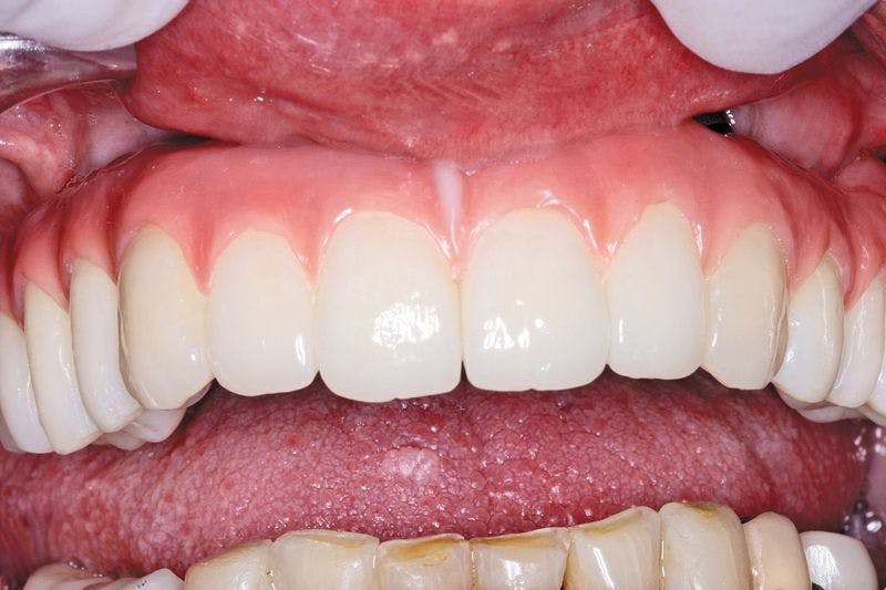


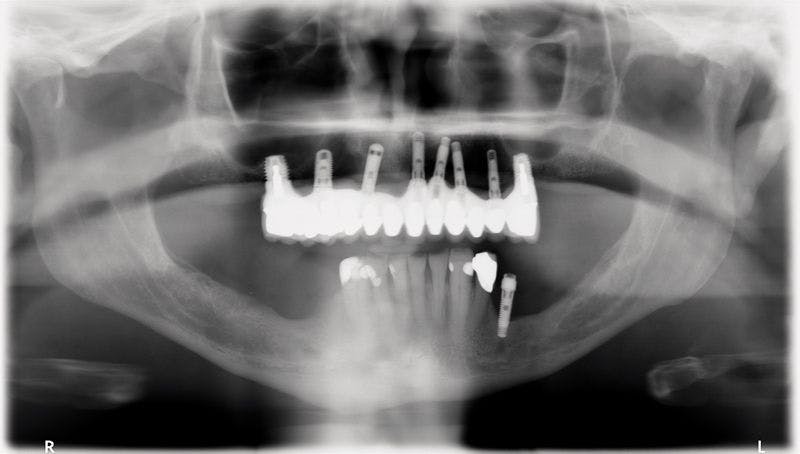

Fig. 14?The definitive restoration in place.
Fig. 15?Panoramic radiograph of the definitive restoration.
Closing Thought
This patient was successfully treated with a CAD/CAM (BellaTek) framework that has been shown to fit accurately on multiple implant connections. Although the patient had received implant from three manufacturers and several were non-optimally placed, the case was recovered successfully by combining conventional prosthodontic principles with advanced implant restorative technologies.
References
1. Drago C, Saldarriaga RL, Domagala D, et al: Volumetric determination of the amount of misfit in CAD/CAM and cast implant frameworks: a multicenter laboratory study. Int J Oral Maxillofac Implants 2010;25:920-929.
2. Takahashi T, Gunne J: Fit of implant frameworks: an in vitro comparison between two fabrication techniques. J Prosthet Dent 2003;89:256-260.
This article originaly appeared in the April 2013 issue of Dental Lab Products. For more great behind-the-scenes articles like this, click here or on the magazine below to subscribe: