How to place an anterior implant using a digital workflow
How to replace a central incisor using socket shield technique.


The patient, a 48-year-old female, is in good general health with no known diseases and not taking any medication. She is a non-smoker with no allergies.
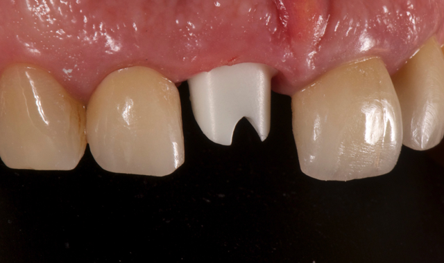
The patient is suffering from the continuous decimation of her crown on the central incisor (Fig. 1). Once the crown is removed, we can see that the remaining stump has subgingival margins and the typical appearance of having suffered continued leaks.
Related reading: How the digital workflow will enhance communication and reliability
The patient’s smile has a high lip line (Fig. 2), shows all incisors and about 4 mm of gum. The restoration requires a highly esthetic result, as any fault would be clearly visible. Patient biotype was average and not very scalloped.
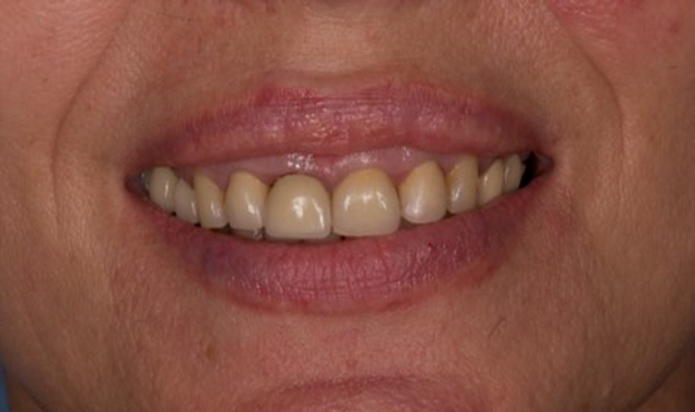


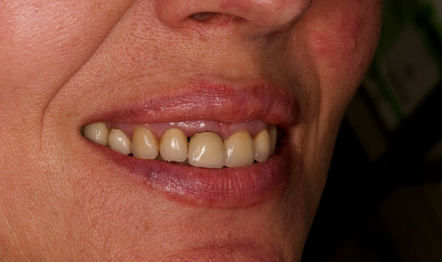
Fig. 1 Fig. 2
Treatment plan
The patient was presented with five treatment options:
1. The first option was to reconstruct the stump and make a new crown. This, however, would not guarantee a predictable treatment in the medium to long-term.
2. The second option was a Maryland bridge together with an alveolar preservation and connective tissue graft. This option was dismissed as the adjacent pieces of a fixed ceramic prosthesis would seriously compromise the adhesion of the Maryland bridge.
3. Option three was an alveolar preservation after the extraction and the subsequent implant placement after 4-5 months in conjunction with a connective tissue graft if necessary.
4. The fourth option, placing the implant early, typically 4-8 weeks after the extraction, was a predictable long-term option with acceptable aesthetic results (Buser 2013).
5. The fifth option, immediate implant, with or without immediate provisionalization and within the immediate procedure, using socket shield technique, was considered the best option. The patient agreed on option five.
Continue to page two to read more...
Treatment description
The first step was the removal of the cemented crown worn by the patient. Once removed (Fig. 3), it was observed that the remaining tooth could not guarantee a fixed restoration over a long-term period.
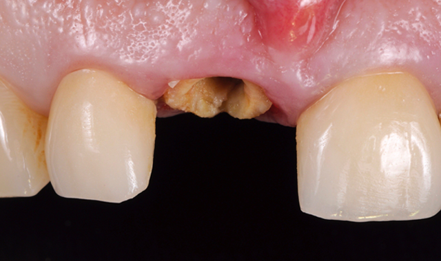


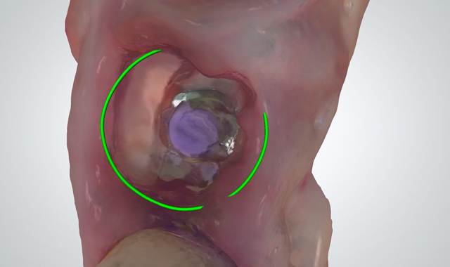
Fig. 3 Fig. 4
After the removal of the crown, we proceeded to the odontosection of the piece mesiodistally. It is important at this point not to touch the interproximal bone during drilling.
Once the odontosection was completed, the extraction of the fragment was made.
Trending article: Why the future looks bright for 3D printing
Using the TRIOS intraoral scanner (3Shape), the scan gave us a clear picture of where the fragment was and enabled us to avoid contact between the provisional restoration and the fragment (Fig. 4).
For this step, it is important that the luxation avoids the support in the interproximal bone as well as the application of force in the vestibular fragment. For this, the luxation must be done from the palatine, preferably with a periotome.
Once the palatine fragment has been extracted, the remaining fragment in the buccal must be regularized. It is important to use long burs to access the apex of the fragment and thus be able to regularize the apical part of the fragment.
In the coronal part, we must reduce the fragment so as to leave 1 mm supracrestal remaining. For this, we drill to about 2 mm subgingival.
Once the fragment is prepared, we proceeded with the usual surgical sequence for the implant system, in this case Phibo® (Barcelona, Spain) Aurea implant. The drilling sequence for a 4.3 mm diameter, 13 mm long RP platform implant was made.
By using a drilling system with a stop incorporated in the drill, the sequence with the drills is carried out for a 14.5 mm implant even if a 13 mm implant is going to be placed. The reason: if we use a drill for a 13 mm long implant, the drilling would not be at a suitable length to place the implant. The cap built into the 13 mm drill would touch the fragment and would not reach the desired length.
After the osteotomy and the creation of neo alveolus, Emdogain® (Straumann, Switzerland) is distributed over the palatine surface of the remaining fragment before placing the implant.
Author’s note: The use of Emdogain® in this procedure is not strictly required. In fact, in later articles, the publisher on the technique (Hürzeler 2010) no longer uses Emdogain® (Bäumer 2013 & Kan 2013).
Clinically, the only noticeable difference is the speed at which the soft tissue heals. In cases using a prosthesis made of PMMA based on a digital impression with a provisional prosthesis, we have observed soft tissue with advanced healing, as compared to the healing when growth factors are not used.
In Bäumer’s article, it is observed that histologically, the only difference is that bone is formed between the fragment and the implant.
Read more: How guided implant surgery can deliver better patient care
The placing of the implant is made to the 35 N•cm initial torque. During the insertion of the implant, we can determine whether there is contact with the fragment or if a gap will be left between the implant and the fragment.
Once the implant is placed in an ideal 3-dimensional position (shoulder 4-5 mm from the gingival margin, slightly toward the palatine with the emergence at the cingulum level of the tooth to be restored and a minimum distance of 1.5 mm from the adjacent teeth), a measurement of the implant’s ISQ is made with a Osstell®. The ISQ in the case of provisionalization of single implants must be at least 70. If it does not reach that ISQ, the implant must be left submerged.
Continue to page three to read more...
Next, we proceed to the placement of the Aurea abutment, which is about 0.8 mm high (Fig. 5), enough to allow the disconnection between the prosthesis and the implant, without the negative effects caused by disconnection, as is the case without an intermediate pillar.
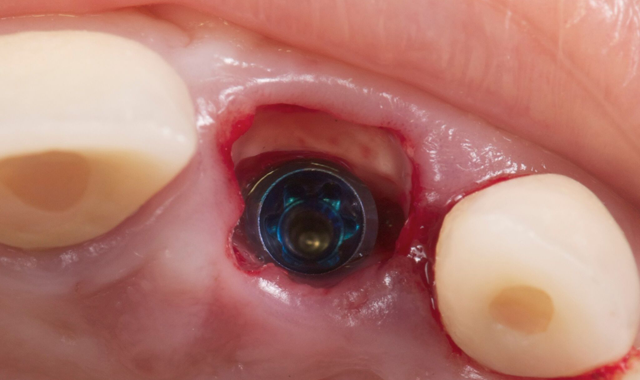

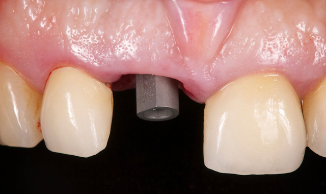

Fig. 5 Fig. 6
We placed the scanning post with the flat side toward the vestibular and digitally scanned the PMMA case for the preparation of the provisional in CAD/CAM (3Shape Dental Designer) in the material of choice (Fig. 6).
Previously, we mentioned why we chose a PMMA made prostheses manufactured with CAD/CAM (Güth JF 2011). The most important advantage is the non-release of monomers from this PMMA against the acrylics normally used in clinic (the release of monomers is related to soft tissue irritation and retraction).
Trending article: The 2017 innovator profiles
Another advantage of a PMMA designed and manufactured with a digital workflow (CAD/CAM) is better mechanical properties and complete control during its design (CAD design).
My intraoral scanning scan strategy is as follows:
1. Scan the antagonist
2. Scan the area where the implant is placed (simply scan the sextant to which the part to be replaced belongs)
3. Scan the implant with the digital scanning post
4. Scan the occlusion
Using the 3Shape TRIOS intraoral scanner, once the scan is made, the order is sent to the laboratory for design of the provisional.
After scanning, we remove the scan post and place a provisional cap on the Aurea abutment. We add the remaining Emdogain® to the area to speed healing.
It is important to provide clear instructions to the laboratory about the characteristics that this provisional must have. The digital scan delivers greater detail of the scanned area by enabling the visualization of the fragment in the digital file. I recommend advising the laboratory to leave 1.5-2 mm distance between the fragment and the provisional.
Another factor to consider is the occlusion. A functional load is not required during the provisionalization period, so the laboratory should be warned to leave the provisional in infra-occlusion.
This provisional is placed 72 hours after the surgery, at about 15 N•cm torque (Fig. 7).
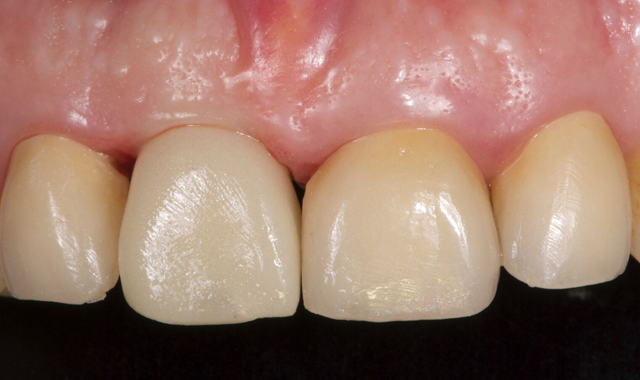

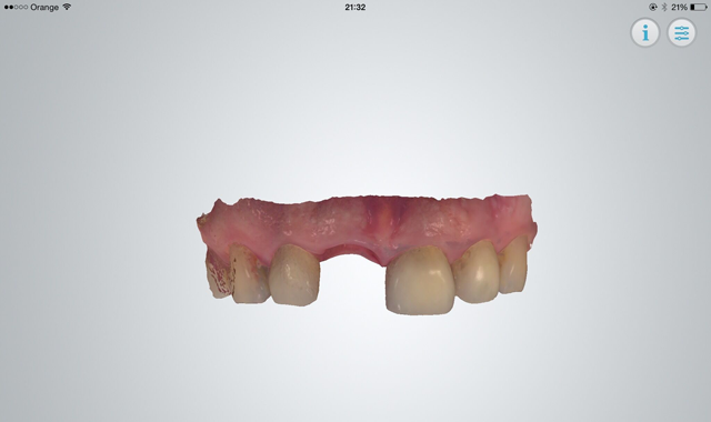

Fig. 7 Fig. 8
Continue to page four to read more...
Prostethic final phase
A new digital print is done after four months, this time with the provisional removed. The emergence profile must be scanned immediately before it starts to collapse (Fig. 8).
After the scan is made, which is the most critical of the four steps to take, we proceed to scan the antagonist, the scanning post and the occlusion.
In this case when the provisional was removed, it was noted that the shield was exposed. There are two ways to avoid continuous contact with the permanent prosthesis (that could cause an infiltration and infection):
Related article: 3Shape strives to make CAD/CAM more affordable for dental laboratories
1. Design the definitive taking the fragment into account and creating a distance of about 1-2 mm from the shield (digital scanning allows a perfect visualization of where the fragment is).
2. Retouch the shield with a diamond bur, which would cause bleeding and coronal epithelialization.
In this case, a zirconium abutment (Fig. 9) was designed to which the porcelain crown is cemented. It is important that the order to the laboratory includes the location of the abutment margin.

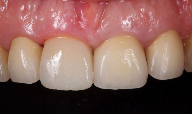
Fig. 9 Fig. 10
This point is critical, since a margin that is too submerged (more than 2 mm subgingival) will complicate the removal of the excess cement (Linkevicius 2011). From 0.5-1 mm subgingival is recommended.
Benefits of the digital workflow
Using a digital workflow, I am able to control every step of the design and manufacture of the provisional and definitive restoration. I would say that for designing the provisional and definitive restorations, the digital workflow is almost mandatory.
Using the TRIOS intraoral scanner gave us a clear vision of where the fragment was. It enabled us to avoid contact between the provisional restoration and the fragment.
For the patient, using an intraoral scanner meant a more minimally invasive procedure and one with a high esthetic outcome (Fig. 10).
In terms of the digital workflow, using 3Shape Communicate™ made the sharing, planning and execution more effective during the design of the provisional and definitive restoration. 3Shape Communicate enabled me to monitor the case workflow across devices
In terms of treatment period, the digital workflow was more efficient and required less visits.