Step-by-step: A better screw-retained zirconia prosthesis
In his debut article for Digital Esthetics, Luke Kahng shows how to create a screw-retained zirconia restoration using CAD/CAM and highly esthetic layering techniques.
For some time now, we have been fabricating screw-retained dentures with great success for the dentist and the patient alike. Using the All-on-4 technique and placement of four-to-six implants, we've created a new and better solution for edentulous patients in need of a denture.


There are two types of restorations we can generate for our patients in need of such service: Traditional Denture or Zirconia Prosthesis. Below we will discuss the pros and cons of the two solutions.
Traditional Denture vs. Zirconia Prosthesis
- Traditional Denture
- Palate covered
- Removable
- Can fall out
- Adhesive may be needed
- Discolorate
- Porous
- Bulky
- Wears out in few years
Introducing Digital Esthetics, the magazine for the digital workflow
Zirconia Prosthesis
- Palateless
- Fixed
- Mounted semi-permanent
- No extra maintenance needed
- Does not change color or stain
- Easier to clean like natural teeth
- Small
- Virtually wear-free
In the author's opinion, a zirconia prosthesis is the better long-term option for this type of denture restoration. It can be utilized with a screw- or cement-retained denture and because the material is heavier than the All-on-4 bar, the restoration mimics nature. His preferred method for this restoration is to layer the material because full monolithic zirconia has too high of a value. Our article will, therefore, involve an actual layered zirconia case.
Click the next button to see the case in action!


Fig. 1 After pouring up impression
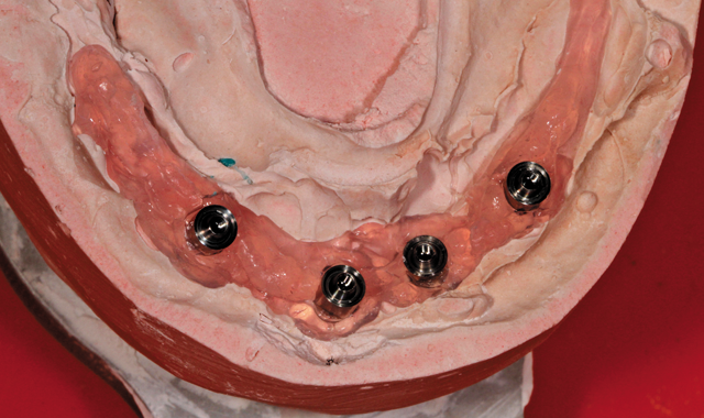
Fig. 1 After pouring up impression
Case study
After pouring up the impression for a case of this nature, the technician's first step should be to make certain there is a verification index completed by the dentist (Fig. 1). If there is not, either the lab technician or the dentist will have to make one for the case. This is because in order to fabricate a screw-retained denture in all one piece, the index is a necessity. The Rx will indicate what the doctor prefers.


Fig. 2 Maxillary duplicate denture
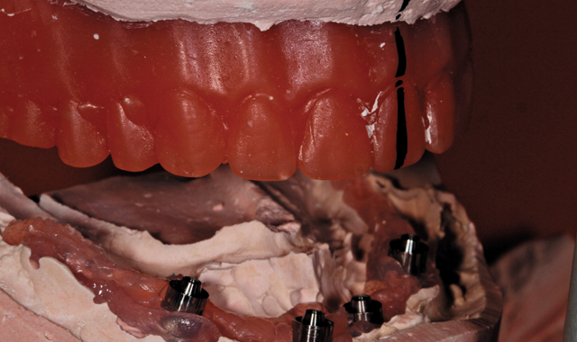
Fig. 2 Maxillary duplicate denture
Next, the technician will need a bite block and to set the teeth-preliminarily-and determine which teeth are in or out, too far, too little, etc. If the implant position is placed too far out in the mouth, it is not possible to fabricate a screw retained denture. The technician will have to examine the appearance of the implants after scanning and discuss his evaluation with the dentist as well as offer options. In our case, it was decided that the best restoration option was layered zirconia, as mentioned previously.
In Figure 2 the reader is given a view of the maxillary duplicate denture. With this particular side angled view of the mounted model, the author observed and verified the mandibular/maxillary occlusion and the length of the occlusion for a correct patient bite.

Fig. 3 Wax try-in
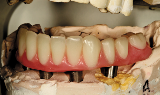
Fig. 3 Wax try-in
In Figure 3, the author has created a wax mandibular try-in for the dentist to try in the patient's mouth. After doing so, and receiving approval from the patient, the dentist sent it back to the lab. The author then mounted it on the cast model and duplicated it, noting teeth size and length. He then did a preliminary scan and design, putting back whatever is necessary to the facial area. During the scan, he could then measure the first cut back on the lower anterior teeth numbers 22-27-approximately a 7/10 inch cut.

Fig. 4 Computer image
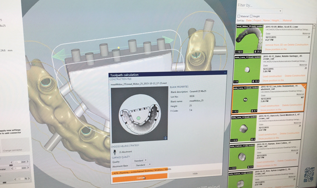
Fig. 4 Computer image
Using a computer program (Fig. 4), the author set up the nesting/before-milling platform. He configured the sprue, thickness inside and out and spread it about evenly to prevent rocking on the model after the sprue was complete.

Fig. 5 In-lab Motion Mill 2 machine
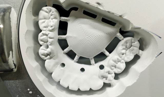
Fig. 5 In-lab Motion Mill 2 machine
Next we have post-milling appearance (Fig. 5), using a Motion Mill 2 machine.

Fig. 6 Gum color for gingival area
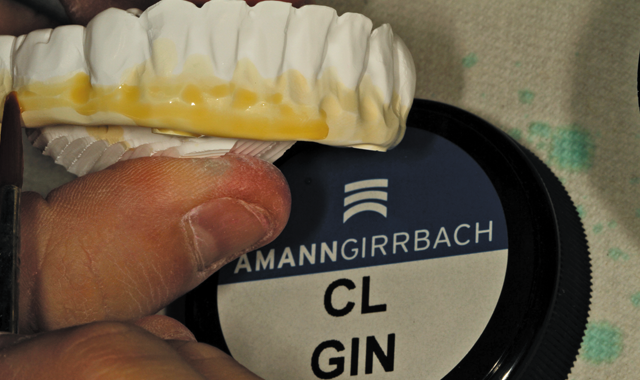
Fig. 6 Gum color for gingival area
The gingival area is orange in color within the thin area pictured in this image (Fig. 6) for numbers 22-27-the actual cut back area we can see through the grinding marks on the model. In order to bring in the gum area for hygienic purposes underneath the denture, the author tweaked his work as much as possible so as to be certain there was not a potential food trap problem for the patient.

Fig. 7 Bottom image pertains to case
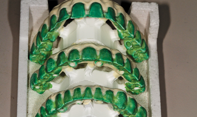
Fig. 7 Bottom image pertains to case
In the next photo, (Fig. 7) we should focus on the third or bottom image as that pertains to this case study. The other two are part of the picture but are involved with regular production cases. The procedure for each is the same regardless-checking for lack of room, etc, in the evaluation. The base color for this case is B1, gingival color chosen was pink.

Fig. 8 Post-sintering, cool down stage
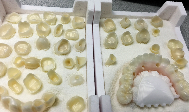
Fig. 8 Post-sintering, cool down stage
After sintering, (Fig. 8), the zirconia copings are left to cool down. The copings in this image are, again, part of the daily production but our attention should be focused upon the zirconia framework which was used for this particular case study.

Fig. 9 GC Initial porcelain colors used for this case
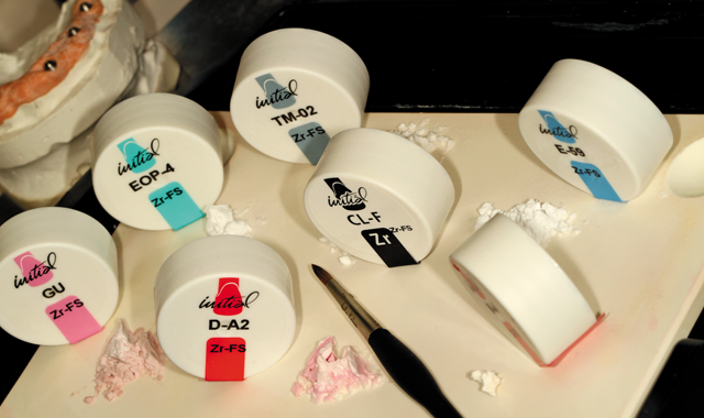
Fig. 9 GC Initial porcelain colors used for this case
In order to create a natural effect for the gum, dentin, translucency and incisal colors, the author used a combination of seven colors, as seen in (Fig. 9).

Fig. 10 First bake
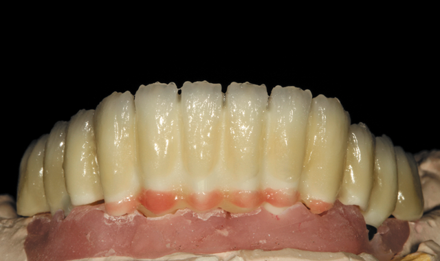
Fig. 10 First bake
After the first bake with gum color, dentin and enamel color were applied to the restoration on the model (Fig. 10). An occlusion view after the first build-up follows (Fig. 11, below).

Fig. 11 Occlusion view, first bake
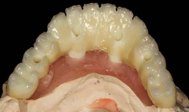
Fig. 11 Occlusion view, first bake

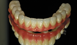
Fig. 12 Final, on the model
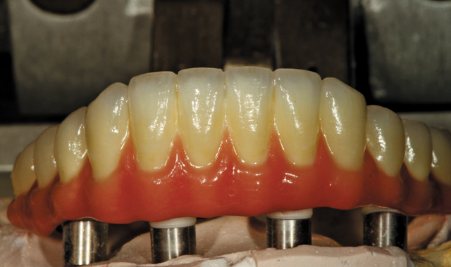
Fig. 12 Final, on the model
Figure 12 shows the final finished restoration, on the model and a mirrored image before the titanium base was cemented (Fig. 13, below), with implant screws included in final. The titanium base was cemented next.

Fig. 13 Mirrored image with implant screws, pre-titanium base cementation
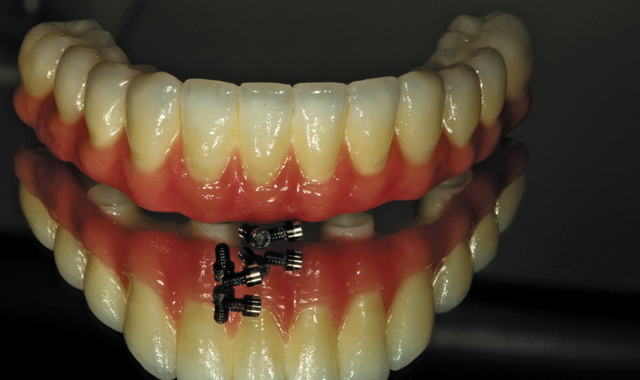
Fig. 13 Mirrored image with implant screws, pre-titanium base cementation
Conclusion
This particular implant case was not so difficult. The steps were: diagnosis, plan, wax try-in stage, PMMA digital scan; then a tooth shape, contour, mid-line, vertical and horizontal line check. The patient tried in the restoration and gave approval. How the restoration is prepared and fabricated depends on the Rx and the patient needs. The author is careful to watch out for rocking on the model in order to prevent breakage. And the final result is a beautiful implant porcelain/zirconia screw-retained denture!